About US
Chassis Systems
We carry out design and development activities for the different varies of the vehicle class, included on steering, suspension, brakes and tire systems, suitable for the market and customer requirements.
Together with new technologies and electric vehicles, we have the competence in the concept and development of chassis systems, project follow-up and supplier management, virtual verification, with modern, light and autonomous vehicle specifications.
- Development and integration of chassis system designs for light commercial vehicles, buses, automobiles, trucks and special class vehicles
- Benchmarking
- Vehicle chassis systems concept selection and technical target settings
- Conceptual design and system development of axle and steering systems
- Wheel and tire selection and vehicle integration
- Determination of material and production method
- 3D CAD model designs and preparation of 2D technical drawings
A few things we’re great at
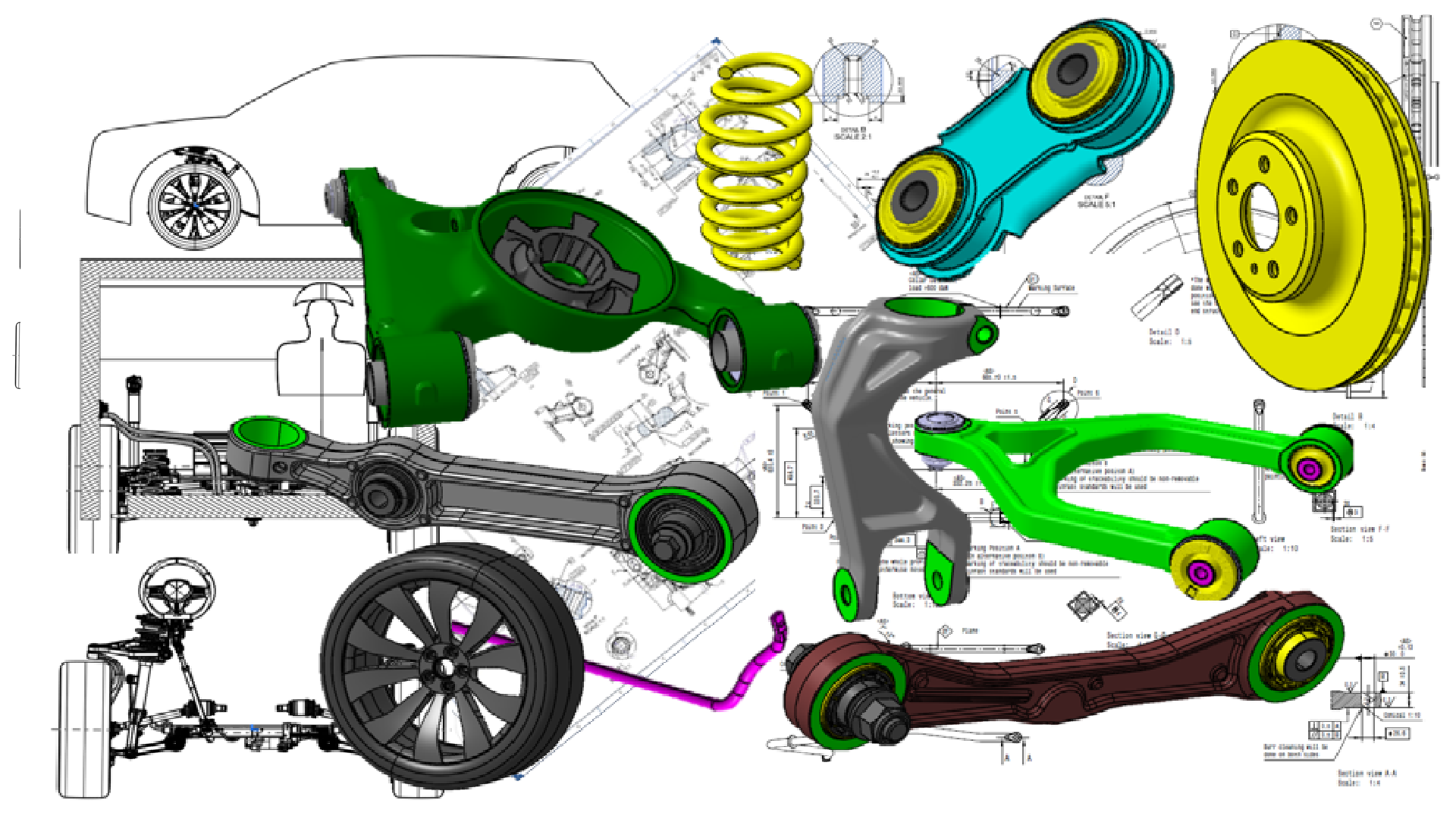
3D CAD model parts & 2D drawing
Requirements and Features:
We define the vehicle’s intended use (e.g. passenger car, off-road vehicle, sports car) and specific performance requirements for the steering, suspension and brakes.
Conceptual design:
We can create a conceptual layout of the chassis, taking into account factors such as weight distribution, packaging constraints and intended vehicle dynamics.
We can choose the type of suspension system (eg independent, solid axle, multi-link) according to the vehicle’s requirements and intended use.
Suspension System Design:
We select the suspension geometry and components (shock absorbers, springs, control arms) that will best provide the desired ride comfort, handling and stability.
We use suspension simulation tools to analyze and optimize the performance of the system under various conditions.
Steering System Design:
We can select the appropriate steering mechanism (rack gear, rotating ball, etc.) according to the size, weight and intended handling characteristics of the vehicle.
We design the steering link, column and components to provide precise and responsive steering control.
Brake System Design:
We can determine the braking requirements according to the weight, speed and intended use of the vehicle.
We select the type of braking system (disc, drum, anti-lock brakes) and properly sized components (calipers, rotors, drums) to meet braking performance targets.
Integration and Packaging:
We ensure that steering, suspension and brake components are properly integrated into the chassis, taking into account packaging constraints and space limitations.
Manufacturing and Production:
We finalize the design for production, taking into account factors such as ease of assembly, cost-effectiveness and scalability.
Supplier selection:
We identify suppliers for various chassis components and collaborate with them so we can ensure quality and on-time delivery.
2D Drawings:
We can make technical drawings and assembly drawings of the chassis parts.
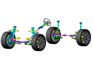
Chassis kinematic architecture
Kinematic Analysis: We can use kinematic analysis. This involves studying the motion and behavior of various components in response to different inputs, such as steering angles, suspension movements, and wheel rotations.
Simulation and Testing: We use the chassis kinematics models from CATIA to simulate and test different driving scenarios such as cornering, braking and rough road conditions.Simulations help us understand how chassis and suspension components interact and make the necessary adjustments to improve vehicle dynamics.
we can design kinematic models of the following suspension types:
– Double wishbone
– Mcpherson
– Multilink suspension
– Rigid axle
– Twist beam
– Active suspension systems
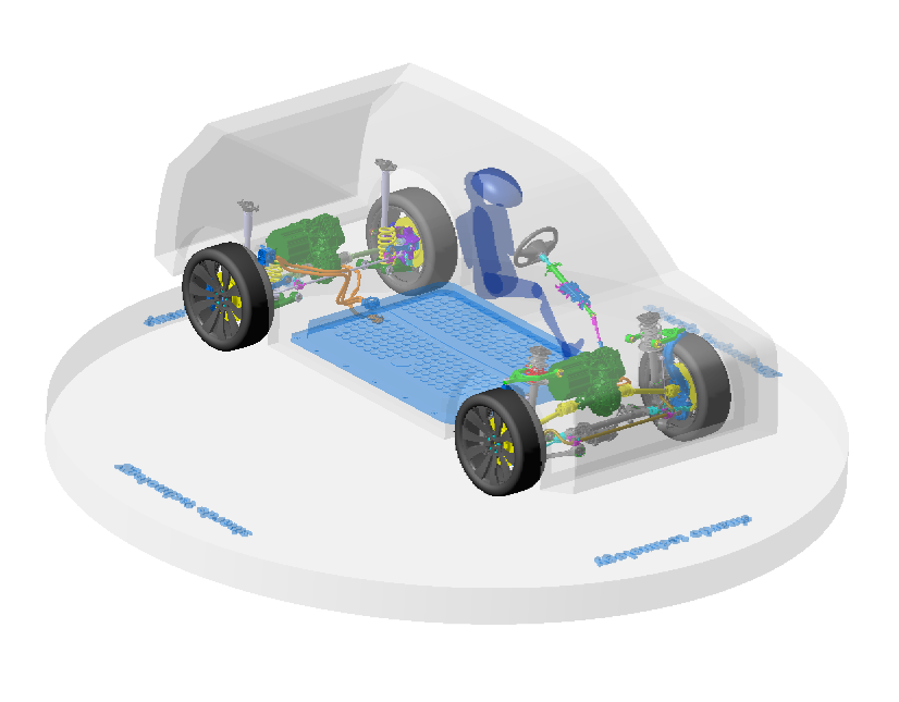
Chassis – PWT Kinematic & Envelopes
We can create a chassis kinematic envelope, commonly used to describe the range of motion and geometric constraints a vehicle’s chassis can accommodate without interference or collision. This envelope defines the maximum and minimum limits of movement of various components within the chassis such as wheels, suspension, steering mechanisms and other related parts.
Manufacturability: The manufacturing process of a vehicle is influenced by the kinematic envelope. Components need to be manufactured and assembled in a way that allows them to operate as intended without violating the envelope’s constraints.
Customization: Where vehicles may have adjustable characteristics (e.g. suspension height, steering characteristics), understanding the kinematic envelope helps us set appropriate limits to avoid excessive adjustments that could compromise safety or performance.
Overall, the chassis kinematic envelope is a critical concept in vehicle design and engineering, helping to ensure that the vehicle operates safely, efficiently, and effectively within the defined range of motion for its various components.
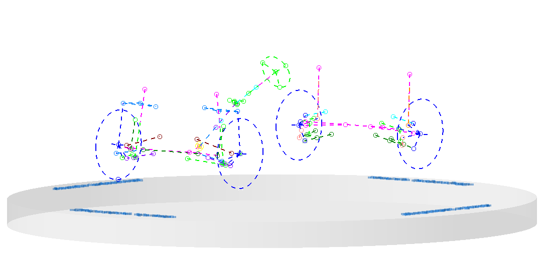
EDU motion & Envelope
While the vehicle is driving, we analyze the movements coming to the EDU (electronic drive unit) with IPS. We use these movements to control the parts around the EDU, at the same time, we observe the bushing movements of the engine.
We create the envelope file using motor movements, then we check the clearances with this envelope.
Sensor cable and brake hose under dynamic effects in the suspension
The dynamic behavior on cables and hoses can play a decisive role in the suspension (sensor cable or brake hose).
Rapid changes in motion or excitation during rebound and compression in the suspension can result in dynamic effects that can be simulated with the dynamic module after the quasi-static design in IPS.
As a result, we use it for virtual validation of dynamic effects on flexible components to examine layout, design space, and durability to reduce hardware prototypes.
Engine hoses – Mechanical behaviour
This design project is about the ideal hose length in the engine compartment, which is required to analyze the stress during engine movement.
For this purpose, we can automatically stretch the hoses from the specified connection points and map the kinematic movement by loading the CAD model of the vehicle into the Simulation program we use. Hose lengths can be changed and the corresponding stress displayed in real time by the software. So we can successfully determine the optimum length. In addition, in this simulation program, Cable Simulation can be used to determine optimum routing with fixing points for clips and hose guides, thus significantly reducing material tension and installation space requirements.
Our Skills
- Catia Cad
- Catia Kinematic
- Catia Envelope
- NX Cad
- NX Motion Simulation
- NX Envelope
- Teamcenter PLM
- Enovia PLM
- IPS Cable Simulation
Our experiences
- C-Suv Project Ev (Chassis system)
- C-Sedan Project Ev (Chassis system)
- B-Suv Project Ev Basic design Benchmarking (Chassis system)
- 10m Electric Bus Project (Chassis system)
- 12m Electric Bus Project (Chassis system)
- 18m Bus Project – Diesel (Chassis system)
- Military Truck Project 4×4 (Chassis system)
- Military Truck Project 8×8 (Chassis system)
- Armoured Police Vehicle Project 4×4 (Chassis system)
- Truck 4×2 – 6×2 – 8×2 air brake systeme designed (road series, construction series)
- Multi Purpose Vehicle (MPV) Chassis system designed ( London taxi project)
- Electric Three Wheeler Project (Chassis system)
- 6m minibus diesel (Chassis system)
- 6m minibus Ev (Chassis system)
Portfolio
OUR main project
our projects
D-Suv Project Ev Chassis system (Only cad studies)
Vehicle features
Front Axle (Double wishbone)
Rear Axle (Multulink)
Testimonials

bakı orcun orgul
Chassis & Powertrain Manager
It’s my absolute pleasure to recommend Fatih Özdemir for design and release engineering activities.
Fatih and I worked at Hexagon Studio together for more than 8 years.
I thoroughly enjoyed my time working with Fatih, and came to know him as a truly valuable asset to absolutely any team. He is honest, dependable and incredibly hard-working. Beyond that, he is an impressive design and release engineer who is always one of the best.
His knowledge of suspension / steering / axle / brake / wheel / driveline and expertise in 3D part modeling (forging, casting, sheet metal), 3D assembly modeling, kinematical analysis, 2D part drawing generation, 2D assembly drawing generation was a huge advantage to our entire office. He put this skillset to work in order to catch the project timeline with extra working if needed.
Along with his undeniable talent, Fatih has always been an absolute joy to work with. He is a true team player, and always manages to foster positive discussions and bring the best out of other employees.
Without a doubt, I confidently recommend Fatih to be a part of your projects. As a dedicated and knowledgeable employee and an all-around great person, I know that he will be a beneficial addition to your organization.

Please feel free to contact me via e – mail (orcunorgul@gmail.com) if you like to discuss Fatih’s qualifications and experience further. I’d be happy to expand on my recommendation.
Best wishes,
Baki Orçun Orgül

burak akyol
EDU System Integration Product Owner
I had a chance to work with Fatih Ozdemir for 3 years in a C-SUV BEV project from scratch. He worked hard on designing a structural support bracket for EDU within a restrained package. His expertise on part envelope creation supported us to analyse various dynamic clearance cases between EDU and surrounding parts. He always demonstrated diligent efforts whenever and wherever support was needed. I appreciated.
Our Team

Fatih Ozdemir
Founder
Chassis Systems Design & Architecture
Contact Us
Fatih Özdemir mobile: +90 555 720 26 33
Yenişehir Mah. Sena sk. No: 10/17 Pendik / İstanbul / Türkiye
fatih.ozdemir@sinardo.com.tr